What is a Filter Press?
While the origin of the term "filter press" is unclear, it most likely refers to the primary function of the equipment as that of a "filter" and the construction of the skeleton as that of a "Press" frame similar to those used in printing and juice processing that were popular at the time presses were developed. Filter presses are sometimes referred to as "Plate-and-Frame Filters". This nomenclature refers to the style of filter element which was most prominent from the filter's development in the mid 1800's until the late 1960's. More recently they are more accurately referred to as "Recessed Plate or Diaphragm (Membrane) Plate Filters" since these are the majority of presses produced for today's markets. These different types are described in detail further on in this section.
In describing what a filter press is, it is best to classify it by the broad categories that differentiate it from other types of liquid/solid separation equipment. Its principle usage is as a "fixed volume, batch pressure filter". As a fixed volume filter, it requires a specific quantity of solids in the total influent stream for the press to work effectively, and if not filled to capacity with solids the filter cake will not reach it's maximum potential for cake dryness. The term "batch" refers to the operation of the press as a cyclical filtering device that requires interruption of the process to discharge the collected solids (filter cake). "Pressure" is used as the drying force in the separation process as opposed to vacuum, gravity, or centrifugal force.
Although not as often, the filter press may also be used as a continuous or "polishing" filter to remove minute quantities of solids from an influent stream (also known as "polishing" the filtrate, hence the name.) In these applications the press is not sized for the quantity of ".batch' or solids holding capacity but for maximum filtration area and hydraulic throughput. When used as a polishing filter the press is usually precoated and generally a dry filter cake is not developed. Rather, when throughput flow rates drop to an unacceptable level the cycle is ended, the solids are discharged, the press is closed and the filtration is restarted.
Another more recent adaptation of the filter press has converted it from a "fixed volume" filter to a "variable volume" filter through the use of a filter plate known as a diaphragm or membrane plate. This type of plate has a flexible drain-field which when sealed around the edges forms an integral bladder or diaphragm that may be inflated to physically press additional liquid from the filter cake. This process can significantly reduce the typical elapsed time for a press cycle and should produce a dry cake product regardless of the quantity of the solids contained in the filter press at the time of diaphragm inflation.
How Does It Work?
The filter press is made up of two principle components. They are the filter pack and the skeleton or press frame. This is true for all filter presses of the "plate-and-frame, recessed plate or diaphragm plate" design and encompasses press frames of both the sidebar and overhead plate suspension types.
The skeleton has one chief function, that is to hold the filter pack together against the pressures developed internally during the filtration process. The terms used to describe the skeleton may vary slightly from manufacturer to manufacturer, but the sub- components remain essentially the same. These components include the stationary head, follower head, closure end and sidebars. Depending on the ancillary equipment supplied, a filter press skeleton may have some additional function such as plate shifting for cake discharge, automatic cake release, or cloth washing (etc.).
The skeleton also provides for the influent and effluent connections with the filter pack. These are the piping connections which pass through the stationary head and connect the feed and discharge manifold to the filter pack.
The filter pack is where the actual liquid/solid separation process takes place. The pack consists of a series of alternating filter elements that, when held together in the press skeleton, form a series of chambers. (Refer to Figure 4.2.) Each chamber wall known as the drain-field, has a series of raised cylinders or grooves which is then covered with a porous cloth medium. These grooves or "pips"(as the cylinders are known) form a flow path for the liquid draining from the press. At alternating comers of the drain-field, interconnecting holes join the drain-field to the four comer discharge ports. When the plates are held together in a plate pack the comer discharge eyes form individual manifolds connecting the drain-fields of the plates with the external piping of the press. The center feed (or less frequently a corner feed) slurry inlet port also forms a manifold which connects with the individual cake collection chambers of the plate pack.
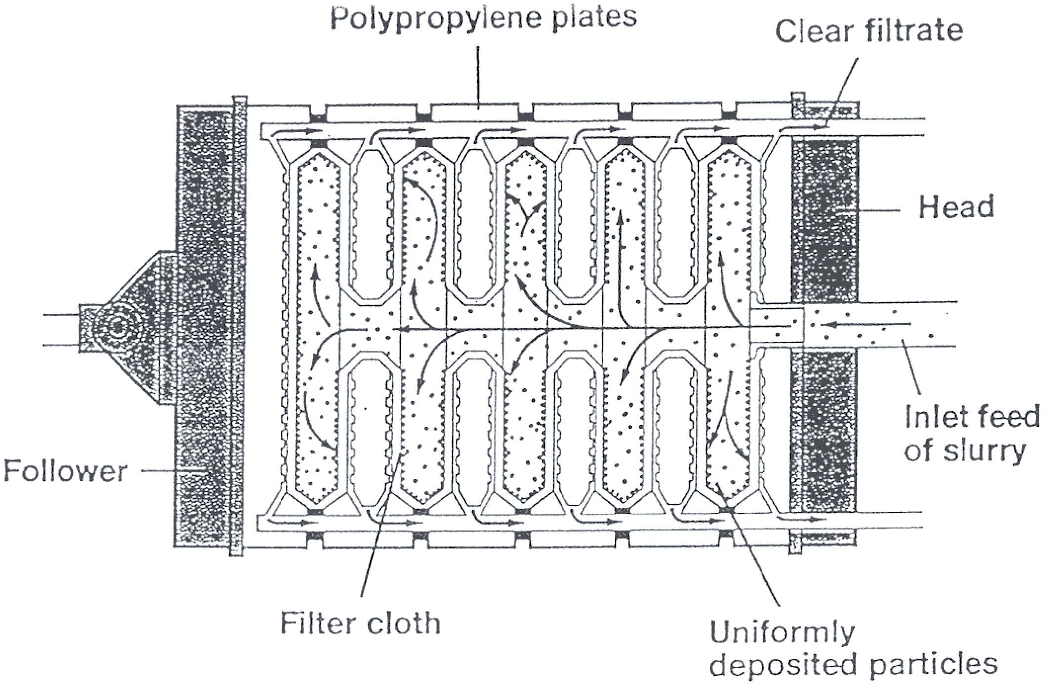 Figure 4.2 Cross Section Of Filter Pack
 In operation, a solids laden slurry is pumped under pressure into the press chambers through the piping at the stationary head of the filter press, via the feed connection. As each cake chamber fills with slurry, the liquid passes through the cloth medium, across the drain-field, through the drain ports and exits via gravity out of the comer discharge eyes.
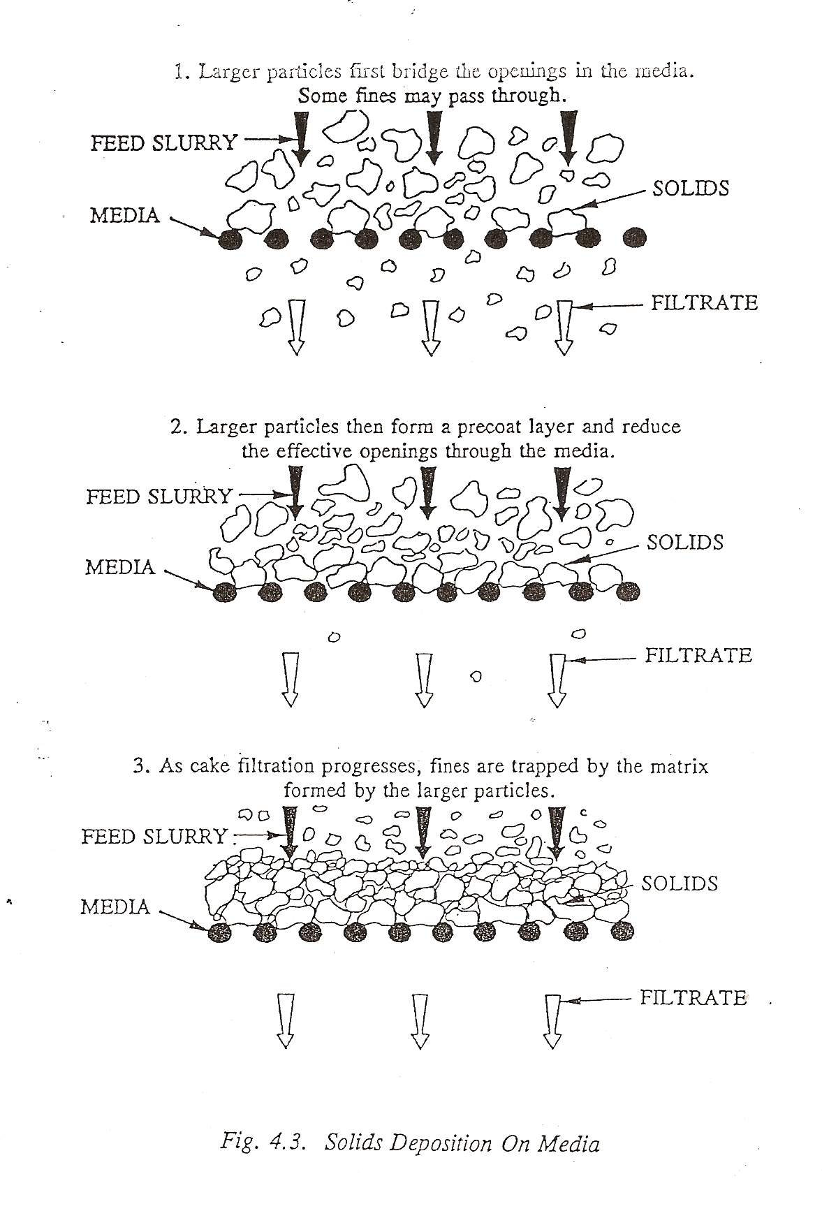
The prime function of the media in cake filtration is to provide a porous support structure for the filter cake as it develops and builds. Initially, some solids may pass through the cloth media causing a slight turbidity in the filtrate, but gradually the larger particles within the slurry begin to bridge the openings in the media reducing the effective opening size. This allows smaller particles to bridge these reduced opening's initiating the cake filtration process. Once a layer of solid particles achieves 1 to 2 mm in thickness, this "precoat" layer serves to separate out finer and finer particles as the cake builds in thickness, yielding a filtrate which is very low in turbidity.
The driving force behind the slurry (typically 100 psi or 7 bar but up to 225 psi or 16 bar) is provided by a positive displacement or, less frequently, a high head centrifugal feed pump. With a gravity drain on the filtrate side of the press, a pressure differential between the feed pressure and the gravity discharge is created across the media and the filter cake solids as they build in thickness. It is the existence of this pressure differential, not just the feed pump pressure, that causes the filtering action to occur. Solids within the slurry will flow to the area of cake development with the lowest pressure differential, resulting in a filter cake which builds uniformly over the drain-field on either side of the chamber walls. This process is the basis for cake filtration and is illustrated in Figure 4-3.
This solids deposition process continues until the filter cakes forming on the individual chamber walls bridge at the center, completely filling the press with solids. It is at this point that the filtration process is complete.
Once this is achieved, the hydraulic closure of the press is retracted, the individual filter elements are separated and the collected solids (filter cake) are discharged, usually by gravity, to an appropriate receptacle.
WHY USE DIFFERENT CAKE THICKNESSES?
During the filtration process, as the filter cake builds in thickness on the media, a concurrent increase of the differential pressure across the cake and a reduction in the rate of filtrate discharge flow occurs. Figure 4-4 represents a typical graph of cumulative filtrate discharge volume versus filtration cycle time. As can be seen, filtrate flow is not constant through out the cycle. At the onset of a filtration cycle when a cake layer does not yet exist and the measured pressure differential is very low or non-existent, flow rates are generally high. The flow rates begin to taper off as the cake builds in thickness and the pressure differential increases. The first one third to one half of the filtration cycle, when the majority of the total cake solids have been pumped into the press, is referred to as the fast fill stage. The balance of the cycle is known as the compaction or consolidation stage. It is during this final stage that the filter cake achieves maximum dryness. When a filter cake is fully developed, the filtrate flow rate will have reached a point at which the reduction in the filtrate flow is so low that the rate appears almost constant. In practice, this rate will become so low that to continue running the filter press would be inefficient. This is the end of the filtration cycle. A general rule of thumb used to determine the end of the filtering cycle is when filtrate discharge rates fall to:
.016 gpm/ft2 of filter area (.65 liters/min./m2)
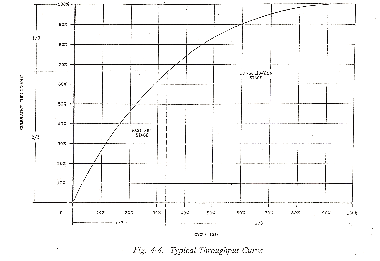 This flow rate may be used as a guideline when first initiating a new filtration application. Every cake product has a different terminal filtrate discharge flow rate based upon cake characteristics and should be developed through experience.
 A factor which impacts the filtrate flow rate is the cake thickness which is being developed. The cake thickness refers to the distance between the drain fields of adjacent filter plates within the closed chambers of the filter pack. Filter elements are available in a number of different cake thicknesses, the common range being 1" (25 mm) to 2" (50 mm) in 1/4" (6-7 mm) increments. Of this range, the most common cake thicknesses are 1" (25 mm) and 1 1/4 " (3 2 mm). However, there are instances that thinner cakes, down to 3/4" (20mm) may be desirable.
The reason for the variety of cake thicknesses is based 'upon the ability of the solids within a liquid/solid suspension to form a porous cake matrix, when filtered, that will allow flow through it as the cake solids build in thickness. As cake thickness builds, differential pressure across the cake increases as does resistance to flow, thus a decrease in filtrate flow rate occurs. Every liquid/solid slurry has a limit as to the thickness of cake that can be developed within a given pressure differential across the thickness of the cake.